
Connecting the Cameras to the Controller
Panasonic PTZ Camera Setup
AW-UE160 + AW-RP150 | LAN Control Configuration
1. Signal Flow
The controller is powered with it's power supply, and the cameras are powered with PoE++ from the injectors. The PoE++ injectors should live on the tech table with the controller and network switch.
The diagram below shows the physical LAN signal path from the camera controller to the robotic cameras.
|
AW-RP150 Camera Controller |
IP CONT → CAT6 |
Unmanaged Network Switch |
Data IN → CAT6 |
PoE Injectors (PoE++ 802.3bt) |
PoE OUT → CAT6 |
AW-UE160 Robotic Camera |
Both PoE injectors must be PoE++ (802.3bt) rated - standard PoE is insufficient to power the AW-UE160.
2. IP Address Configuration
Both devices must reside on the same subnet with unique IP addresses. The confirmed working configuration is as follows:
|
Device |
IP Address |
Subnet Mask |
|
AW-UE160 Camera |
192.168.0.21 thru 29 |
255.255.255.0 |
|
AW-RP150 Controller |
192.168.0.10 thru 12 |
255.255.255.0 |
Note: Every camera and controller have been set with their own IP addresses. They are labeled on the cameras. Please DO NOT change the IP addresses.
3. Camera to Controller Setup
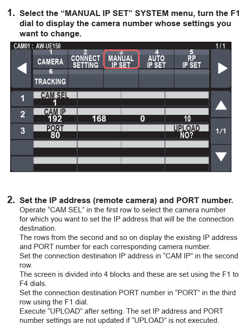
4. Easy IP SETUP TOOL - Panasonic
1) If, for any reason you need to go into the the Easy IP SETUP TOOL.exe for the unit the username and password are below:
Username: markeys | Password: 2909